Quick reference for the RP2
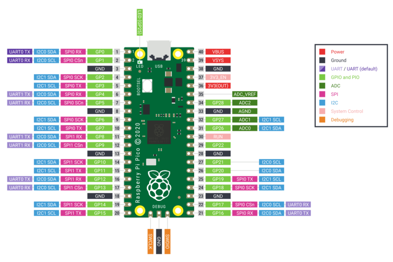
The Raspberry Pi Pico Development Board (image attribution: Raspberry Pi Foundation).
Below is a quick reference for Raspberry Pi RP2xxx boards. If it is your first time working with this board it may be useful to get an overview of the microcontroller:
Installing MicroPython
See the corresponding section of tutorial: Getting started with MicroPython on the RP2xxx. It also includes a troubleshooting subsection.
General board control
The MicroPython REPL is accessed via the USB serial port. Tab-completion is useful to find out what methods an object has. Paste mode (ctrl-E) is useful to paste a large slab of Python code into the REPL.
The machine module:
machine.freq() allows to change the MCU frequency and control the peripheral frequency for UART and SPI. Usage:
machine.freq(MCU_frequency[, peripheral_frequency=48_000_000])
The MCU frequency can be set in a range from less than 48 MHz to about 250MHz. The default at boot time is 125 MHz. The peripheral frequency must be either 48 MHz or identical to the MCU frequency, with 48 MHz as the default. If the peripheral frequency is changed, any already existing instance of UART and SPI will change it’s baud rate and may have to be re-configured:
import machine

machine.freq()          # get the current frequency of the CPU
machine.freq(240000000) # set the CPU frequency to 240 MHz and keep
                        # the UART frequency at 48MHz
machine.freq(125000000, 125000000) # set the CPU and UART frequency to 125 MHz
The rp2 module:
import rp2
Networking
WLAN
Note
This section applies only to devices that include WiFi support, such as the Pico W and Pico 2 W.
The network.WLAN class in the network module:
import network

wlan = network.WLAN()       # create station interface (the default, see below for an access point interface)
wlan.active(True)           # activate the interface
wlan.scan()                 # scan for access points
wlan.isconnected()          # check if the station is connected to an AP
wlan.connect('ssid', 'key') # connect to an AP
wlan.config('mac')          # get the interface's MAC address
wlan.ipconfig('addr4')      # get the interface's IPv4 addresses

ap = network.WLAN(network.WLAN.IF_AP) # create access-point interface
ap.config(ssid='RP2-AP')              # set the SSID of the access point
ap.config(max_clients=10)             # set how many clients can connect to the network
ap.active(True)                       # activate the interface
A useful function for connecting to your local WiFi network is:
def do_connect():
    import machine, network
    wlan = network.WLAN()
    wlan.active(True)
    if not wlan.isconnected():
        print('connecting to network...')
        wlan.connect('ssid', 'key')
        while not wlan.isconnected():
            machine.idle()
    print('network config:', wlan.ipconfig('addr4'))
Once the network is established the socket module can be used
to create and use TCP/UDP sockets as usual, and the requests module for
convenient HTTP requests.
After a call to wlan.connect(), the device will by default retry to connect
forever, even when the authentication failed or no AP is in range.
wlan.status() will return network.STAT_CONNECTING in this state until a
connection succeeds or the interface gets disabled.
Delay and timing
Use the time module:
import time

time.sleep(1)           # sleep for 1 second
time.sleep_ms(500)      # sleep for 500 milliseconds
time.sleep_us(10)       # sleep for 10 microseconds
start = time.ticks_ms() # get millisecond counter
delta = time.ticks_diff(time.ticks_ms(), start) # compute time difference
Timers
RP2040’s system timer peripheral provides a global microsecond timebase and generates interrupts for it. The software timer is available currently, and there are unlimited number of them (memory permitting). There is no need to specify the timer id (id=-1 is supported at the moment) as it will default to this.
Use the machine.Timer class:
from machine import Timer

tim = Timer(period=5000, mode=Timer.ONE_SHOT, callback=lambda t:print(1))
tim.init(period=2000, mode=Timer.PERIODIC, callback=lambda t:print(2))
By default, timer callbacks run as soft IRQs so they can allocate but
are prone to GC jitter and delays. Pass hard=True to the Timer()
constructor or init() method to run the callback in hard-IRQ context
instead. This reduces delay and jitter, but see Writing interrupt handlers for the
restrictions that apply to hard-IRQ handlers.
Pins and GPIO
Use the machine.Pin class:
from machine import Pin

p0 = Pin(0, Pin.OUT)    # create output pin on GPIO0
p0.on()                 # set pin to "on" (high) level
p0.off()                # set pin to "off" (low) level
p0.value(1)             # set pin to on/high

p2 = Pin(2, Pin.IN)     # create input pin on GPIO2
print(p2.value())       # get value, 0 or 1

p4 = Pin(4, Pin.IN, Pin.PULL_UP) # enable internal pull-up resistor
p5 = Pin(5, Pin.OUT, value=1) # set pin high on creation
Programmable IO (PIO)
PIO is useful to build low-level IO interfaces from scratch. See the rp2 module
for detailed explanation of the assembly instructions.
Example using PIO to blink an LED at 1Hz:
from machine import Pin
import rp2

@rp2.asm_pio(set_init=rp2.PIO.OUT_LOW)
def blink_1hz():
    # Cycles: 1 + 7 + 32 * (30 + 1) = 1000
    set(pins, 1)
    set(x, 31)                  [6]
    label("delay_high")
    nop()                       [29]
    jmp(x_dec, "delay_high")

    # Cycles: 1 + 7 + 32 * (30 + 1) = 1000
    set(pins, 0)
    set(x, 31)                  [6]
    label("delay_low")
    nop()                       [29]
    jmp(x_dec, "delay_low")

# Create and start a StateMachine with blink_1hz, outputting on Pin(25)
sm = rp2.StateMachine(0, blink_1hz, freq=2000, set_base=Pin(25))
sm.active(1)
UART (serial bus)
There are two UARTs, UART0 and UART1. UART0 can be mapped to GPIO 0/1, 12/13 and 16/17, and UART1 to GPIO 4/5 and 8/9.
See machine.UART.
from machine import UART, Pin
uart1 = UART(1, baudrate=9600, tx=Pin(4), rx=Pin(5))
uart1.write('hello')  # write 5 bytes
uart1.read(5)         # read up to 5 bytes
Note
REPL over UART is disabled by default. You can see the Getting started with MicroPython on the RP2xxx for details on how to enable REPL over UART.
PWM (pulse width modulation)
There are 8 independent PWM generators called slices, which each have two channels making it 16 PWM channels in total which can be clocked from 8Hz to 62.5Mhz at a machine.freq() of 125Mhz. The two channels of a slice run at the same frequency, but can have a different duty rate. The two channels are usually assigned to adjacent GPIO pin pairs with even/odd numbers. So GPIO0 and GPIO1 are at slice 0, GPIO2 and GPIO3 are at slice 1, and so on. A certain channel can be assigned to different GPIO pins (see Pinout). For instance slice 0, channel A can be assigned to both GPIO0 and GPIO16.
Use the machine.PWM class:
from machine import Pin, PWM

# create PWM object from a pin and set the frequency of slice 0
# and duty cycle for channel A
pwm0 = PWM(Pin(0), freq=2000, duty_u16=32768)
pwm0.freq()             # get the current frequency of slice 0
pwm0.freq(1000)         # set/change the frequency of slice 0
pwm0.duty_u16()         # get the current duty cycle of channel A, range 0-65535
pwm0.duty_u16(200)      # set the duty cycle of channel A, range 0-65535
pwm0.duty_u16(0)        # stop the output at channel A
print(pwm0)             # show the properties of the PWM object.
pwm0.deinit()           # turn off PWM of slice 0, stopping channels A and B
ADC (analog to digital conversion)
RP2040 has five ADC channels in total, four of which are 12-bit SAR based ADCs: GP26, GP27, GP28 and GP29. The input signal for ADC0, ADC1, ADC2 and ADC3 can be connected with GP26, GP27, GP28, GP29 respectively (On Pico board, GP29 is connected to VSYS). The standard ADC range is 0-3.3V. The fifth channel is connected to the in-built temperature sensor and can be used for measuring the temperature.
Use the machine.ADC class:
from machine import ADC, Pin
adc = ADC(Pin(26))     # create ADC object on ADC pin
adc.read_u16()         # read value, 0-65535 across voltage range 0.0v - 3.3v
The argument of the constructor ADC specifies either a Pin by number, name of as Pin object, or a channel number in the range 0 - 3 or ADC.CORE_TEMP for the internal temperature sensor. If a pin is specified, the pin is initialized in high-Z mode. If a channel number is used, the pin is not initialized and configuring is left to the user code. After hard reset, RP2040 pins operate in current sink mode at about 60µA. If the pin is not otherwise configured, that may lead to wrong ADC readings.
Software SPI bus
Software SPI (using bit-banging) works on all pins, and is accessed via the machine.SoftSPI class:
from machine import Pin, SoftSPI

# construct a SoftSPI bus on the given pins
# polarity is the idle state of SCK
# phase=0 means sample on the first edge of SCK, phase=1 means the second
spi = SoftSPI(baudrate=100_000, polarity=1, phase=0, sck=Pin(0), mosi=Pin(2), miso=Pin(4))

spi.init(baudrate=200000) # set the baudrate

spi.read(10)            # read 10 bytes on MISO
spi.read(10, 0xff)      # read 10 bytes while outputting 0xff on MOSI

buf = bytearray(50)     # create a buffer
spi.readinto(buf)       # read into the given buffer (reads 50 bytes in this case)
spi.readinto(buf, 0xff) # read into the given buffer and output 0xff on MOSI

spi.write(b'12345')     # write 5 bytes on MOSI

buf = bytearray(4)      # create a buffer
spi.write_readinto(b'1234', buf) # write to MOSI and read from MISO into the buffer
spi.write_readinto(buf, buf) # write buf to MOSI and read MISO back into buf
Warning
Currently all of sck, mosi and miso must be specified when
initialising Software SPI.
Hardware SPI bus
The RP2040 has 2 hardware SPI buses which is accessed via the machine.SPI class and has the same methods as software SPI above:
from machine import Pin, SPI

spi = SPI(1, 10_000_000)  # Default assignment: sck=Pin(10), mosi=Pin(11), miso=Pin(8)
spi = SPI(1, 10_000_000, sck=Pin(14), mosi=Pin(15), miso=Pin(12))
spi = SPI(0, baudrate=80_000_000, polarity=0, phase=0, bits=8, sck=Pin(6), mosi=Pin(7), miso=Pin(4))
Software I2C bus
Software I2C (using bit-banging) works on all output-capable pins, and is accessed via the machine.SoftI2C class:
from machine import Pin, SoftI2C

i2c = SoftI2C(scl=Pin(5), sda=Pin(4), freq=100_000)

i2c.scan()              # scan for devices

i2c.readfrom(0x3a, 4)   # read 4 bytes from device with address 0x3a
i2c.writeto(0x3a, '12') # write '12' to device with address 0x3a

buf = bytearray(10)     # create a buffer with 10 bytes
i2c.writeto(0x3a, buf)  # write the given buffer to the peripheral
Hardware I2C bus
The driver is accessed via the machine.I2C class and has the same methods as software I2C above:
from machine import Pin, I2C

i2c = I2C(0)   # default assignment for Pico: scl=Pin(5), sda=Pin(4)
i2c = I2C(1, scl=Pin(3), sda=Pin(2), freq=400_000)
I2S bus
See machine.I2S.
from machine import I2S, Pin

i2s = I2S(0, sck=Pin(16), ws=Pin(17), sd=Pin(18), mode=I2S.TX, bits=16, format=I2S.STEREO, rate=44100, ibuf=40000) # create I2S object
i2s.write(buf)             # write buffer of audio samples to I2S device

i2s = I2S(1, sck=Pin(0), ws=Pin(1), sd=Pin(2), mode=I2S.RX, bits=16, format=I2S.MONO, rate=22050, ibuf=40000) # create I2S object
i2s.readinto(buf)          # fill buffer with audio samples from I2S device
The ws pin number must be one greater than the sck pin number.
The I2S class is currently available as a Technical Preview. During the preview period, feedback from users is encouraged. Based on this feedback, the I2S class API and implementation may be changed.
Two I2S buses are supported with id=0 and id=1.
Real time clock (RTC)
See machine.RTC
from machine import RTC

rtc = RTC()
rtc.datetime((2017, 8, 23, 0, 1, 12, 48, 0)) # set a specific date and
                                             # time, eg. 2017/8/23 1:12:48
                                             # the day-of-week value is ignored
rtc.datetime() # get date and time
WDT (Watchdog timer)
The RP2040 has a watchdog which is a countdown timer that can restart parts of the chip if it reaches zero.
See machine.WDT.
from machine import WDT

# enable the WDT with a timeout of 5s (1s is the minimum)
wdt = WDT(timeout=5000)
wdt.feed()
The maximum value for timeout is 8388 ms.
OneWire driver
The OneWire driver is implemented in software and works on all pins:
from machine import Pin
import onewire

ow = onewire.OneWire(Pin(12)) # create a OneWire bus on GPIO12
ow.scan()               # return a list of devices on the bus
ow.reset()              # reset the bus
ow.readbyte()           # read a byte
ow.writebyte(0x12)      # write a byte on the bus
ow.write('123')         # write bytes on the bus
ow.select_rom(b'12345678') # select a specific device by its ROM code
There is a specific driver for DS18S20 and DS18B20 devices:
import time, ds18x20
ds = ds18x20.DS18X20(ow)
roms = ds.scan()
ds.convert_temp()
time.sleep_ms(750)
for rom in roms:
    print(ds.read_temp(rom))
Be sure to put a 4.7k pull-up resistor on the data line. Note that
the convert_temp() method must be called each time you want to
sample the temperature.
NeoPixel and APA106 driver
Use the neopixel and apa106 modules:
from machine import Pin
from neopixel import NeoPixel

pin = Pin(0, Pin.OUT)   # set GPIO0 to output to drive NeoPixels
np = NeoPixel(pin, 8)   # create NeoPixel driver on GPIO0 for 8 pixels
np[0] = (255, 255, 255) # set the first pixel to white
np.write()              # write data to all pixels
r, g, b = np[0]         # get first pixel colour
The APA106 driver extends NeoPixel, but internally uses a different colour order:
from apa106 import APA106
ap = APA106(pin, 8)
r, g, b = ap[0]
APA102 (DotStar) uses a different driver as it has an additional clock pin.