Quick reference for the PSOC™ Edge
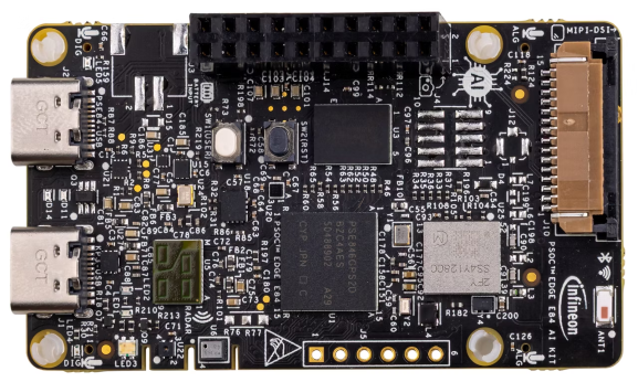
Below is a quick reference for PSOC™ Edge E84 boards. If it is your first time working with this port it may be useful to get an overview of the microcontroller:
Note
You can follow the latest progress for this port in the Infineon MicroPython PSOC™ Edge fork. We are working to bring those features here. Meanwhile, you can try them early by installing the fork version.
Pins and GPIO
See machine.Pin for the complete Pin API reference. This section focuses on the specific PSOC™ Edge port variations and particularities.
The constructor
The controller pin naming follows the nomenclature P<port>_<pin>, where:
<port>is a numeric identifier for the port (e.g., 0-21 for the PSOC™ Edge E84)
<pin>is the pin number within that port.
Use the respective board pinout diagram to find the available pins and their locations.
This is the id that needs to be passed to the constructor in one of the following formats:
As a string label, single or double quoted:
'P<port>_<pin>'or"P<port>_<pin>"A pre-instantiated object
Pin.cpu.<pin>orPin.board.<pin>.
from machine import Pin

p_in  = Pin('P0_0', Pin.IN)
p_out = Pin("P7_0", Pin.OUT, value=False)

p = Pin(Pin.cpu.P17_1, Pin.OPEN_DRAIN)
The pre-instantiated object can be used directly without calling the constructor.
Instead, you can use init() to configure it.
from machine import Pin

pin = Pin.cpu.P17_0
pin.init(mode=Pin.IN)
Tip
Use the REPL interface to discover the available user pins, using tab for completion:
>>> from machine import Pin
>>> Pin.cpu.P
P10_5           P10_7           P11_3           P12_3
P13_0           P13_1           P13_2           P13_3
P13_4           P13_5           P13_6           P13_7
P14_0           P14_1           P14_2           P14_3
P14_4           P14_5           P14_6           P14_7
P15_0           P15_1           P15_2           P15_3
P15_4           P15_5           P15_6           P15_7
P16_0           P16_1           P16_2           P16_3
P16_4           P16_5           P16_6           P16_7
P17_0           P17_1           P17_2           P17_3
P17_4           P17_5           P17_7           P20_3
P20_4           P20_5           P20_6           P20_7
P21_1           P21_2           P21_3           P21_4
P21_5           P21_6           P21_7           P3_0
P3_1            P6_4            P6_6            P7_0
P7_7            P8_0            P8_1            P8_5
P8_6            P9_0            P9_1            P9_2
P9_3
>>> from machine import Pin
>>> Pin.board.
AMIC1_CTB_INN   AMIC1_CTB_INP   AMIC1_CTB_OUT   AMIC1_CTB_REF
AMIC2_CTB_INN   AMIC2_CTB_INP   AMIC2_CTB_OUT   AMIC2_CTB_REF
I2C_SCL_1V8     I2C_SCL_3V3     I2C_SDA_1V8     I2C_SDA_3V3
I2S_TX_FYSYNC   I2S_TX_MCK      I2S_TX_SCK      I2S_TX_SD
I3C_SCL         I3C_SDA         IMU0_INT        IMU1_INT
MAG_INT         PDM_CLK         PDM_DATA        PRESS_SENS_INT
RADAR_INT       RADAR_RESET     RADAR_SPI_CLK   RADAR_SPI_CS
RADAR_SPI_MISO  RADAR_SPI_MOSI  SERIAL_INT0     SERIAL_INT1
SERIAL_INT2     SERIAL_INT3     USER_BUTTON     USER_LED1
USER_LED2       USER_LED_B      USER_LED_G      USER_LED_R
The drive parameter accepts up to 8 levels, which set the following drive strength for the pin:
DRIVE_0: 1mA/2mA drive current (normal/high speed IO)
DRIVE_1: 2mA/4mA drive current (normal/high speed IO)
DRIVE_2: 3mA/6mA drive current (normal/high speed IO)
DRIVE_3: 4mA/8mA drive current (normal/high speed IO)
DRIVE_4: 5mA/10mA drive current (normal/high speed IO)
DRIVE_5: 6mA/12mA drive current (normal/high speed IO)
DRIVE_6: 7mA/14mA drive current (normal/high speed IO)
DRIVE_7: 8mA/16mA drive current (normal/high speed IO)
For more information about drive strength, check the PSOC™ Edge Datasheet and Architecture Reference Manual.
Note
The following constructor arguments and/or configuration values are NOT supported in this port:
alt: Alternate functionality is not supported.
mode:Pin.ALT,Pin.ALT_OPEN_DRAIN, andPin.ANALOGmodes are not supported.
The following mode- pull combinations are not supported in this port:
Pin.OUTwithPin.PULL_UPorPin.PULL_DOWN
Pin.OPEN_DRAINwithPin.PULL_DOWN
Methods
- Pin.irq(handler=None, trigger=Pin.IRQ_FALLING | Pin.IRQ_RISING, priority=7)
The following parameters have port-specific behavior:
priority: Priority values range from 7 (lowest) to 0 (highest). Default is 7.Note
All pins on the same port share the same interrupt line. Therefore, only one priority can be set for all pins on the same port. If multiple pins configure interrupts for the same port, the highest priority will be used. If only one pin is configured for an interrupt, its priority can be reconfigured to any value.
Note
The following irq() features are not supported in this port:
trigger: ThePin.IRQ_LOW_LEVELandPin.IRQ_HIGH_LEVELtriggers are not supported.
wake: The wake parameter is currently not supported.
hard: This parameter is ignored. It can be passed but currently has no effect.
Note
None of the non-core methods from the Pin API are currently implemented for this port.
Real time clock (RTC)
See machine.RTC:
from machine import RTC
import time

irq_counter = 0

def cback(event):
    global irq_counter
    irq_counter += 1

rtc = RTC()
rtc.init((2023, 1, 1, 0, 0, 0, 0, 0)) # initialise rtc with specific date and time,
                                      # eg. 2023/1/1 00:00:00
rtc.datetime((2017, 8, 23, 2, 12, 48, 0, 0)) # set a specific date and
                                             # time, eg. 2017/8/23 1:12:48
rtc.datetime() # get date and time

rtc.irq(trigger=RTC.ALARM0, handler=cback)
rtc.alarm(1000, repeat=False) # set one-shot short alarm in ms
rtc.alarm_left() # Read the time left for the alarm to expire
time.sleep_ms(1008) # wait sufficient time
print(irq_counter) # Check irq counter

rtc.irq(trigger=RTC.ALARM0, handler=cback)
rtc.alarm(3000, repeat=True) # set periodic short alarm in ms
rtc.cancel() # cancel the alarm

rtc.irq(trigger=RTC.ALARM0, handler=cback)
rtc.alarm((2023, 1, 1, 0, 0, 1, 0, 0), repeat=False) # set one-shot longer duration alarm

rtc.memory(b"hello") # write bytes into RTC user memory
rtc.memory() # read bytes from RTC user memory
Note
Setting a random week day in ‘wday’ field is not valid. The underlying library implements the logic to always calculate the right weekday based on the year, date and month passed. However, datetime() will not raise an error for this but rather re-write the field with the last calculated actual value.
Note
RTC API behavior on this port has the following specifics:
RTC()is a singleton constructor with noidor additional constructor arguments.rtc.irq()accepts alarm trigger0(RTC.ALARM0);wakeis not implemented.rtc.alarm()acceptstimeand optionalrepeat; no positional alarmidargument is used.Input
weekdayin datetime tuples is ignored and hardware computes the weekday from date fields.The current
rtc.memory([data])maximum payload on KIT_PSE84_AI is 28 bytes.
Warning
RTC alarm timing on this port has second-level resolution. Millisecond alarm values are accepted, but are rounded up to whole seconds internally.
UART
See machine.UART.
The following specialization applies to this port:
Constructor
- class UART(id)
The following parameters are supported with limited configuration:
bits. Only 8 bits.
These are planned for future implementation, but yet unavailable:
rtsctsflow
Note
These parameters are not implemented:
txbufinvert
Methods
- UART.init(baudrate=9600, bits=8, parity=None, stop=1, *, ...)
The same parameters as the constructor are supported, with the same limitations.